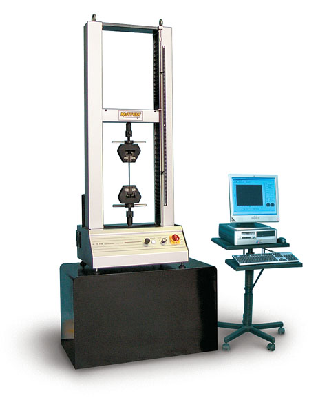
ELECTROMECHANICAL MACHINE 50 kN
This machine is designed to be used in Laboratories for Quality Control and Research on Metals, Plastics, Composed Materials, Wires, Ropes, Paper, Textiles etc.
This model is suitable to make tensile and elongation tests on different materials following the EN 10002 / EN ISO 6892, 7500-1 and ASTM A370 Standards.
The machine is composed by a strong base containing the transmission components and the Hardware control instruments.
The base carries two columns that guide the cross-bar; they are made of high resistance steel with ground hard chrome surfacing. The big diameter and the position where the columns are fitted grant a high lateral rigidity. The system is suitable to realise both tests with single direction or dual direction.
In order to grant no clearance, the transmission of the movement to the mobile cross-bar takes place through two re-circulating spheres screws with pre-loaded female screws.
High attention is given to the assembling system of the screws and their groups - bearings put in the base and in the upper head.
The mobile cross-bar with big section together with all other elements of the machine being properly dimensioned grant a very good “Rigidity of the machine” (UNI ISO 5893 Standards).
The moving up and down of the cross bar on the columns happens through sintered bushes with low friction coefficient.
On the mobile cross-bar there are some holes for the mounting of the load cells.
The Load Cell is made in stainless steel and reads both tensile and compression loads with a very high precision.
It is in conformity with the EN 10002-2 / EN ISO 6892, 7500-1 Standards.
Features of the load cell referred to ISO 376 Standards.
- Accuracy class 1
- Repeatability error ≤ ± 0.145%
- Interpolation error ≤ ± 0.090 %
- Error on zero ≤ ± 0.03 %
- Reversibility error ≤ ± 0.240%
- Non linearity error ≤ ± 0.04 %
- Maximum overload capacity 200%
In order to follow the specific needs of each single application, different load cells with different capacities within the nominal capacity of the machine can be installed on the frame.
Different connections for the installation of the seizing devices are on the mobile cross-bar and on the base (see accessories pages).
The machine is delivered with different safety devices limiting the maximum travel of the cross-bar. There is also an adjustable device that allows setting a personalised upper and lower travel limit following the used appliances.
The control section is made by a series of cards inside the base of the machine that are managing the control units and the reading units positioned on the machine. The acquisition card, with a powerful microprocessor and converter AD 24 bits, takes all the working dates and through a RS232 connection it sends all these dates to the Personal Computer, which controls all the functions of the machine and makes the elaboration of all the calculations through the program UTM WIN.
On the base there are:
- a device which allows an easy and speedy positioning of the mobile cross-bar.
- a push button to interrupt the test execution at any time.
- a series of connectors for the connection to the control PC and to the auxiliaries appliances (extensometer, load cells etc.)
- general switch/Safety switch.
The frames protecting the columns and the screws are made of anodised aluminium, the internal sides are closed with anti-dust bellows and all the outside and internal parts are properly treated against the corrosion.
Following equipments are not delivered with the machine and have consequently to be ordered separately:
- Personal computer model H009-01 (indispensable for the working of the machine).
- Standard UTM 2 software model H009 (indispensable for the working of the appliance).
- Special personalised programs (following the customer demand).
- Accessories for the seizing of the specimens.
- Printer model C128
- Extensometers model H014
- Other accessories
- The voltage must not have peaks of tension, over-tensions and transitory over-currents or drops of voltage higher than 10% of the nominal voltage.
- Working temperature from +10° C. up to +38° C.
- Humidity range from +10% up to +90%, without condensation.
NOTES RELEVANT TO THE FIRST TABLE (SEE BELOW):
(*) The cross bar travel is referred to the distance between the upper surface of the base and the lower surface of the cross bar and it doesn’t include the load cell, the seizing devices, the different equipments etc.
(**) The vertical opening of the testing chamber is the distance between the upper surface of the base and the lower surface of the crossbar, without load cells, seizing devices and other devices.
(***) The maximum distance between the tensile heads is the distance between the grips when the crossbar is at its upper dead point (load cell is installed). Practically it is the free length of the specimen between the tensile heads.
ELECTROMECHANICAL MACHINE 10 kN
This machine is designed to be used in Laboratories for Quality Control and Research on Metals, Plastics, Composed Materials, Wires, Ropes, Paper, Textiles etc.
This model is suitable to make tensile and elongation tests on different materials following the EN 10002 / EN ISO 6892, 7500-1 and ASTM A370 Standards.
The machine is composed by a strong base containing the transmission components and the Hardware control instruments.
The base carries two columns that guide the cross-bar; they are made of high resistance steel with ground hard chrome surfacing. The big diameter and the position where the columns are fitted grant a high lateral rigidity. The system is suitable to realise both tests with single direction or dual direction.
In order to grant no clearance, the transmission of the movement to the mobile cross-bar takes place through two re-circulating spheres screws with pre-loaded female screws.
High attention is given to the assembling system of the screws and their groups - bearings put in the base and in the upper head.
The mobile cross-bar with big section together with all other elements of the machine being properly dimensioned grant a very good “Rigidity of the machine” (UNI ISO 5893 Standards).
The moving up and down of the cross bar on the columns happens through sintered bushes with low friction coefficient.
On the mobile cross-bar there are some holes for the mounting of the load cells.
The Load Cell is made in stainless steel and reads both tensile and compression loads with a very high precision.
It is in conformity with the EN 10002-2 / EN ISO 6892, 7500-1 Standards.
Features of the load cell referred to ISO 376 Standards.
- Accuracy class 1
- Repeatability error ≤ ± 0.145%
- Interpolation error ≤ ± 0.090 %
- Error on zero ≤ ± 0.03 %
- Reversibility error ≤ ± 0.240%
- Non linearity error ≤ ± 0.04 %
- Maximum overload capacity 200%
In order to follow the specific needs of each single application, different load cells with different capacities within the nominal capacity of the machine can be installed on the frame.
Different connections for the installation of the seizing devices are on the mobile cross-bar and on the base (see accessories pages).
The machine is delivered with different safety devices limiting the maximum travel of the cross-bar. There is also an adjustable device that allows setting a personalised upper and lower travel limit following the used appliances.
The control section is made by a series of cards inside the base of the machine that are managing the control units and the reading units positioned on the machine. The acquisition card, with a powerful microprocessor and converter AD 24 bits, takes all the working dates and through a RS232 connection it sends all these dates to the Personal Computer, which controls all the functions of the machine and makes the elaboration of all the calculations through the program UTM WIN.
On the base there are:
- a device which allows an easy and speedy positioning of the mobile cross-bar.
- a push button to interrupt the test execution at any time.
- a series of connectors for the connection to the control PC and to the auxiliaries appliances (extensometer, load cells etc.)
- general switch/Safety switch.
The frames protecting the columns and the screws are made of anodised aluminium, the internal sides are closed with anti-dust bellows and all the outside and internal parts are properly treated against the corrosion.
Following equipments are not delivered with the machine and have consequently to be ordered separately:
- Personal computer model H009-01 (indispensable for the working of the machine).
- Standard UTM 2 software model H009 (indispensable for the working of the appliance).
- Special personalised programs (following the customer demand).
- Accessories for the seizing of the specimens.
- Printer model C128
- Extensometers model H014
- Other accessories
- The voltage must not have peaks of tension, over-tensions and transitory over-currents or drops of voltage higher than 10% of the nominal voltage.
- Working temperature from +10° C. up to +38° C.
- Humidity range from +10% up to +90%, without condensation.
NOTES RELEVANT TO THE FIRST TABLE (SEE BELOW):
(*) The cross bar travel is referred to the distance between the upper surface of the base and the lower surface of the cross bar and it doesn’t include the load cell, the seizing devices, the different equipments etc.
(**) The vertical opening of the testing chamber is the distance between the upper surface of the base and the lower surface of the crossbar, without load cells, seizing devices and other devices.
(***) The maximum distance between the tensile heads is the distance between the grips when the crossbar is at its upper dead point (load cell is installed). Practically it is the free length of the specimen between the tensile heads.
UNIVERSAL HYDRAULIC SERVO-CONTROLLED MACHINE, 600 kN, FOR STATIC TENSILE TESTS
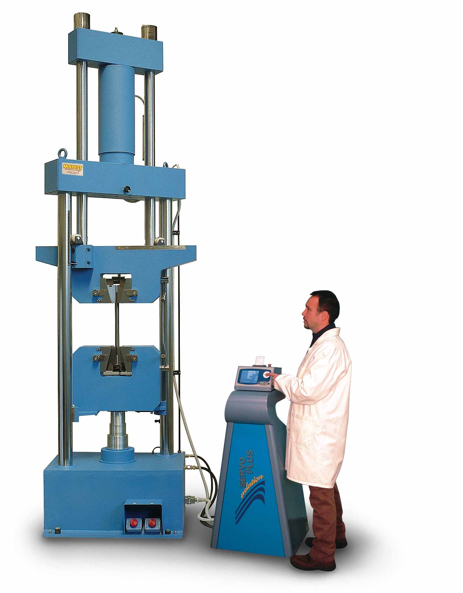
Universal hydraulic servo-controlled machine 600 kN capacity with touch-screen digital system, to perform static tensile tests on metallic materials.
It basically consists of:
- Strong loading frame with a reading cell built into the piston
- Hydraulic Servo-Plus Evolution Touch-Screen system for the data acquisition, control and processing. The whole is built in a console.
The frame is designed to carry out tensile tests using the grips placed in the clamping heads. In the upper part, between the head and traverse, it is possible to carry out flexion, compression, bending, hardness, dishing tests, according to the International Standards by using the suitable (see accessories) devices.
The hydraulic servocontrolled unit regulates the load rate by the Computer. An emergency device stops the machine in any moment as per the International Safety Standards.
A control pedal situated on the frame governs the movement of the lower tensile head (excursion 0÷580mm with electric end of stroke switches) for an easier positioning of the specimen according to its length. The machine is supplied complete with loading frame, control console and bed frame, while the software (mod. H009), the extensometers (mod. H014 to H014-10) the grips and the printer “are options and must be ordered separately” according to the needs of the user.
TECHNICAL FEATURES:
Capacity 600kN
Max. crosshead stroke 200 mm
Max. distance between the jaws 465 mm
Width flexion joke 190 mm
Max. flexion knives distance 1000 mm
Compression plates light 235 mm
Load reading Sensing by loading cell
Resolution 0,01% U.V.
Accuracy Class 1 EN 10002-2
Only reading scale 1:1-1:20 U.V.
Stroke reading Sensing by linear transducer
Resolution 0,01 mm
Deformation reading Sensing by electronic extensometer (accessory)
Resolution 0,001 mm
Accuracy Class B 2 (B 1 for base up to 50 mm) ASTM E83
Needed height 4050 mm
Frame weight 2600 kg approx.
Rack dimensions 610x630xh.1600 mm
Power supply 230 V 1ph 50Hz 2kW
H003-99 KIT FOR MACHINE DELIVERY
The kit is composed by different mechanical devices to flatwise the machine allowing its transport. The amount of this kit is fully reimbursed to the customer if the kit is returned to Matest after the delivery.
HYDRAULIC SERVO-CONTROLLED MACHINE, 600 kN, FOR STATIC TENSILE TESTS
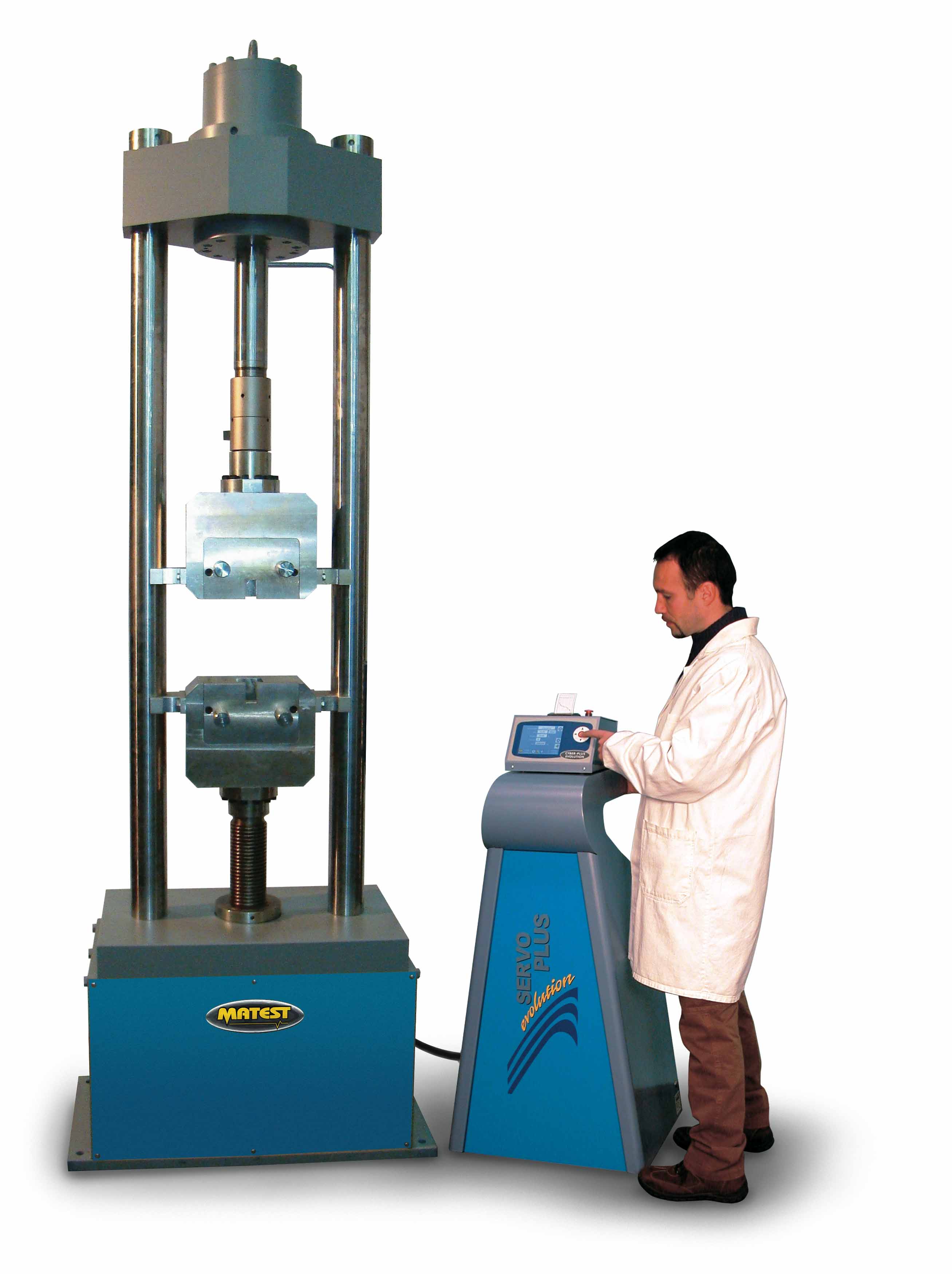
The machine basically consists of :
- Sturdy loading frame with electric cell for load reading and built in piston displacement transducer
- Hydraulic unit and Servo-Plus Evolution Touch-Screen system.
The frame is designed to perform tensile tests using the jaws placed in the clamping heads, in accordance with the mentioned International Standards.
The hydraulic servo-controlled unit regulates the load rate. An emergency device allows to stop the machine at any moment as per CE Safety Standards.
The lower tensile head can be adjusted in height through an electric motor, for an easier positioning of the specimen according to its length. Jaws are pneumatically activated through a compressor (accessory mod. V206).
The machine is supplied complete with loading frame and control console, while PC (H009-01), software (H009N),jaws, printer and extensometers (H014 to H014-10) are optional accessries and have to be ordered separately according to the operator needs.
TECHNICAL SPECIFICATIONS:
- Capacity: 600kN
- Distance between jaws min/max: 100/800mm
- Suitable distance between jaws for test: 450mm
- Upper hydraulic loading piston: stroke 300mm
- Lower tensile head: stroke 400mm
- Ideal distance between jaws for tests: 500mm
- Daylight between vertical columns: 440mm
- Load reading: Sensing by load cell. Resolution 0,01% U.V.
- Accuracy: Class 1 EN 10002-2
- Stroke reading: Sensing by linear transducer. Resolution 0,01mm
- Needed height: 3200mm
- Frame dimensions: 860x480x3000mm
- Console dimensions: 610x630x1600mm
Total weight 2200kg approx.
Power supply 400V 3ph+neutral+earth 50Hz 2kW